
Published: August 31, 2026 | 8 Min Read
What Causes CT Saturation and How Can It Be Prevented?
A protection relay that refuses to trip during a genuine fault is every substation engineer’s nightmare, and more often than not, the real culprit hiding behind that failure is CT saturation. As a CT PT Transformer Manufacturer supplying protection and metering cores across India, LES Ecotonik System sees this issue resurface again and again during commissioning and fault investigation. Current transformer saturation distorts the secondary waveform exactly when accurate data matters most. If the relay engineer does not understand why, an entire protection scheme can quietly fail. Here is what actually drives CT saturation, and how good design keeps it from happening.
Inside a Current Transformer: Why Saturation Happens at All
Every CT has a magnetic core with limited ability to carry flux. As primary current rises, the core needs proportionally more flux to reproduce it accurately. Push past a point called the knee point voltage, and the core stops keeping up. The output waveform flattens and distorts instead of tracking true current, and the relay downstream starts receiving bad information at the worst possible moment.
The Real Triggers Behind Current Transformer Saturation
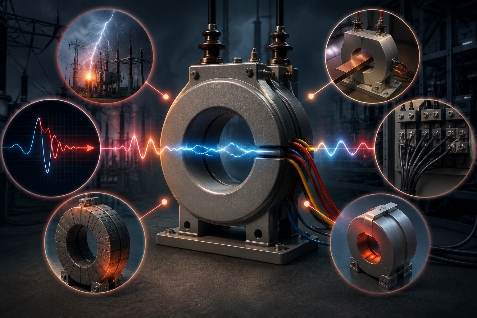
A handful of field conditions cause most saturation events, and they rarely act alone.
- Heavy fault current with DC offset. A nearby fault can carry an asymmetrical DC component that drives saturation far faster than the symmetrical RMS value suggests.
- Wrong CT ratio. A ratio picked without checking maximum fault current leaves no margin, so the core saturates before the relay sees the full fault.
- Burden exceeding rated VA. Long cable runs, extra meters on the same core, or undersized cable cross-section all add resistance beyond the CT’s design burden.
- Residual flux from a previous fault. Cores do not always demagnetize fully after a trip, lowering the threshold for the next saturation event.
- Core material shortfalls. Low-grade silicon steel or an undersized core limits achievable knee point voltage from the start.
Where Saturation Problems Usually Originate
CT saturation can originate from several design and operating conditions. The following illustrative distribution shows how different causes can contribute to field saturation cases.
Root Cause & Illustrative Share of Field Cases
- Fault current with DC offset – 35%
- Incorrect CT ratio selection – 25%
- Excessive secondary burden – 20%
- Residual or remnant flux – 12%
- Core material or design shortfall – 8%
*Figures reflect commonly reported field patterns during protection audits and are a directional guide for design review, not a certified statistic.
How Saturation Undermines Your Protection Relay
Once a CT saturates, secondary current no longer mirrors the primary fault accurately. Differential relays can see a false mismatch and trip when they should not, while overcurrent relays can under-read the fault and delay tripping past the coordination time set for that zone. In a differential or busbar zone, a saturated CT is often the single biggest reason behind a maloperation report.
Prevention Strategies That Actually Work
- Size the CT ratio against maximum fault current , not just normal load current, so the core has headroom before it approaches saturation.
- Keep secondary burden inside rated VA by shortening cable runs and separating protection cores from metering cores.
- Choose a low-remanence core design where fast auto-reclose is expected, so residual flux does not stack up between events.
- Verify with saturation curve testing before commissioning, not after a nuisance trip forces a site investigation.
Choosing the Right CT PT Transformer Manufacturer Makes the Difference
Correct sizing on paper only helps if the manufacturer builds to that knee point voltage and burden specification, batch after batch. LES Ecotonik System designs CT and PT units around documented saturation curves, so protection engineers get the margin they specify rather than a best-effort approximation.
Frequently Asked Questions
It is the point on a CT’s excitation curve where further voltage increase gives disproportionately little current gain, marking the practical accuracy ceiling.
Yes. A ratio chosen without checking maximum fault current leaves little margin, even if the CT looks correctly rated for normal load.
Usually not, but it can send a distorted signal that causes a missed, delayed, or unwanted trip.
Yes, especially after repeated faults or fast auto-reclose, since cores rarely demagnetize completely between events.
Final Word
CT saturation is rarely one dramatic failure. It is usually a quiet stack of undersized ratio, excess burden, and inadequate knee point voltage that only shows up when a real fault tests the system.
Specify correctly at the design stage, verify with saturation curve data, and work with a current transformer manufacturer who documents that data rather than hiding it in a generic catalog.
Need Help With Your CT Specification?
Get in touch with our engineering team to review your CT specification, or visit the LES Ecotonik System for our complete protection range.