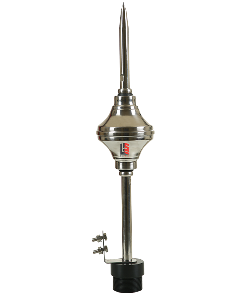
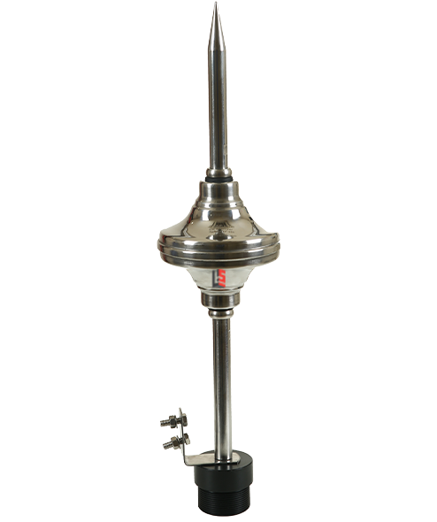
STORMFLASH 15

Home » Archives for bypilot

Description

During a storm the ambient electric field may rise from 600 V to 10-20 kV/m. When the electric field reach this level representing a minimum risk for a lightning, the StormFlash begins to get activated and generates high voltage pulses, helping to create and propagating an upward leader. After a strike on the StormFlash, the lightning current is driven to ground by the down conductor to the earth termination system.

Features

  • Early Streamer Emission (ESE) Air Terminal
  • NF C 17-102 (edition 2011) and UNE 21186: 2011 standards
  • ΔT = 15 μSec (Triggering Time Advance ΔT)
  • No need of battery or external power source
  • 304L (Inox) Stainless Steel design-suitable for any environmental conditions
  • Suitable for use with a variety of down conductors – tape/strip, round conductor, isolated/insulated cables/HVSC Cable etc
  • 20 years warranty
Mast Height h(m) Level I (Very High) Level II (High) Level III (Medium) Level IV (Standard)
2 13 15 18 20
3 19 22 27 31
4 25 30 36 41
5 32 37 45 51
6 32 38 46 52
8 33 39 47 54
10 34 40 49 56
20 35 44 55 63
30 35 44 58 69
40 35 44 60 72

STORMFLASH 60

Home » Archives for bypilot

Description

During a storm the ambient electric field may rise from 600 V to 10-20 kV/m. When the electric field reach this level representing a minimum risk for a lightning, the StormFlash begins to get activated and generates high voltage pulses, helping to create and propagating an upward leader. After a strike on the StormFlash, the lightning current is driven to ground by the down conductor to the earth termination system.

Features

  • Early Streamer Emission (ESE) Air Terminal
  • NF C 17-102 (edition 2011) and UNE 21186: 2011 standards
  • ΔT = 60 μSec (Triggering Time Advance ΔT)
  • No need of battery or external power source
  • 304L (Inox) Stainless Steel design-suitable for any environmental conditions
  • Suitable for use with a variety of down conductors – tape/strip, round conductor, isolated/insulated cables/HVSC Cable etc
  • 20 years warranty
  • 70 kA (8/20 µSec) Impulse Current – CPRI (Government of India) tested
Mast Height h(m) Level I (Very High) Level II (High) Level III (Medium) Level IV (Standard)
2 31 35 39 43
3 47 52 58 63
4 63 69 78 85
5 79 86 97 107
6 79 87 97 107
8 79 88 98 108
10 79 88 99 109
15 80 89 101 111
20 80 89 102 113
45 80 89 105 119
50 80 89 105 120
80 80 89 105 120
100 80 89 105 120

LIGHTNING STRIKE RECORDER

Home » Archives for bypilot

Description

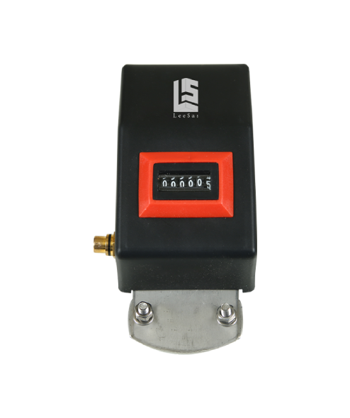
Lightning strike recorder is designed to count and record the lightning strikes captured by lightning protection systems such as ESE lightning rods, simple capturing rods and the cage method. The Lightning strike recorder is necessary to determine whether the lightning rod received any lightning strikes.

The counter is connected to the down conductor of the lightning arrester and therefore it detects the electromagnetic field caused by lightning discharge current and it counts each strike and shows it by way of the number display.With the help of the Lightning strike recorder the customer can follow the number of lightning strikes arrested by system.

Features

  • IP 65 rated enclosure suitable for external application
  • Ease of installation, Flashcount can be retrofitted to any lightning protection system
  • Non-intrusive and fast acting proximity circuit detects lightning transient currents
  • Non resettable electro-mechanical counter
  • Can be mounted at any location along the down conducto
Model LS-LSR6
Description Lightning strike Recorder
Display Model ​ Electro mechanical display (non re-settable)
Current Sensitive Mode Inductive Probe (Built – In)
Operating temperature (oC) -20 +85
Current Sensitivity (8/20 μs) >250A
Lightning Current (10/350 μs) 100 KA
Indicator 6 Digits
Degree of protection IP 65 (IEC 529)
Enclosure Material Plastic
Dimension of Counter (cm) 16 (L) X 9 (W) X 6 (H)
Testing Facility Testing Jack inbuilt in Counter and Customer can test anytime in field

CT & PT

Home » Archives for bypilot

Description

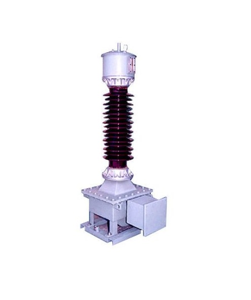
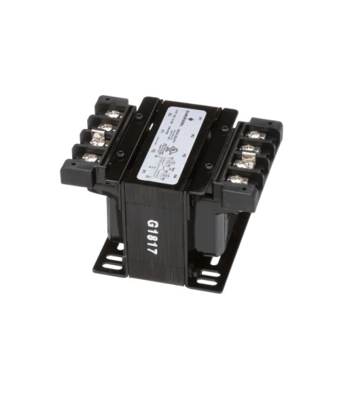
Potential transformers are also known as voltage transformers and they are basically step down transformers with extremely accurate turns ratio. Potential transformers step down the voltage of high magnitude to a lower voltage which can be measured with standard measuring instrument.

Features

These transformers have large number of primary turns and smaller number of secondary turns.
A potential transformer is typically expressed in primary to secondary voltage ratio. For example, a 600:120 PT would mean the voltage across secondary is 120 volts when primary voltage is 600 volts.


INSTRUMENTATION TRANSFORMER

Home » Archives for bypilot

Description

Instrument transformers are designed to transform voltage or current from high values in the transmission and distribution systems to low values that can be utilized by low voltage metering and relay devices. The three phase combined instrument transformers are used in distribution systems up to 33kV level due to techno economic feasibility.

Features

Lightning impulse test is a type test, and is performed to evaluate instrument transformer insulation strength to withstand lightning impulse voltages. This paper discusses about the different lightning impulse testing practices of the three phase combined instrument transformer and their relevance to the procedures stipulated in the National and International standards.


CABLE TO CABLE

Home » Archives for bypilot

Description

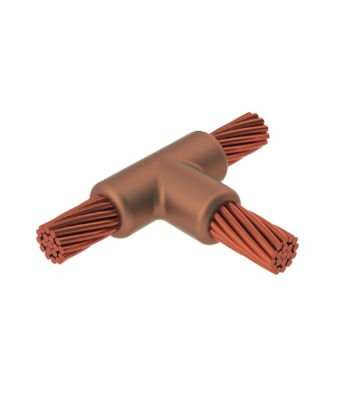
This takes place quickly and safely inside a graphite mould. The mould is designed specifically for a certain union depending on the elements to be welded and the joint type required. We guarantee all types of joints plus it is especially useful for joining dissimilar metals.

Features

  • Fine designing.
  • Easy to install.
  • Require less maintenance.
  • Size: 80*80*200 mm.
  • Material: High Density Graphite.
  • Color: Brown.
 

STRIKERX LIGHTNING STRIKE COUNTER

Home » Archives for bypilot

Description

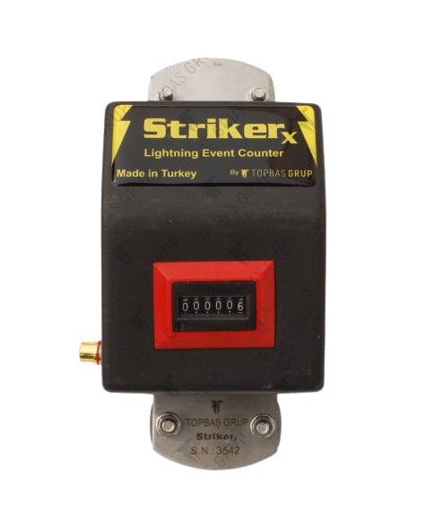
StrikerX is designed to sense, record and count the lightning strikes captured by lightning protection system such as ESE Air Terminal, Normal Lightning Rod, Cage Method, Rolling Sphere Method system.

StrikerX is connected to the lightning down conductor. The flow of lightning current to the counter terminals is sensed and counted by the electromechanical device fitted inside. With every pass by lightning strike through the counter, the customer can follow the number of strikes with the count displayed.

StrikerX Lightning Strike Counter does not require any additional or external power source for its operation. The counter is provided with the testing jack so that the customers can check the working condition on field.

Features

  • IP 65 rated enclosure suitable for external application.
  • Ease of installaion, StrikerX can be retro-fitted to any lightning protection system.
  • Non-intrusive and fast acting proximity circuit detects lightning transient currents.
  • Non re-settable electro-mechanical counter.
Model StrikerX
Display 6 Digits Electromechanical Display (non re-settable)
Current Sample Mode Inductive Probe (Built-in)
Current Sensitivity (8/20 µs) >250A
Lightning Current (10/350 µs) 100 kA
Operating Temperature (°C) -20~+85
Enclosure Material Plastic
Degree of Protection IP 65 (IEC 529)
Dimension (cm) 107 (L) x 64 (W) x 53 (H)

LYRA ESE AIR TERMINAL

Home » Archives for bypilot

Description

Standard

  • NF C 17-102 (2011) designed & tested

Design

  • Non-Electronic ESE (In-built Triggering Device)
  • No use of battery or external power source.
  • 304L (Inox) Stainless Steel – suitable for any environmental conditions.

Specification

Testing

  • Delta T, ΔT=10 µSec (Triggering Time Advance).
  • CE certified.

Usability

  • Suitable for various down conductors Round/Flat (Bare & Insulated), Cables, etc
Protection radius as per NF C 17-102 (2011)
Mast Height h (m) Level I Very High Level II High Level III Medium
2 10 12 15
3 15 19 23
4 21 25 30
5 26 31 38
6 27 32 39
7 27 33 39
8 27 33 39

UMBRAECO ESE AIR TERMINAL

Home » Archives for bypilot

Description

Standard

  • NF C 17-102 (2011) designed & tested

Design

  • Non-Electronic ESE (In-built Triggering Device)
  • No use of battery or external power source.
  • 304L (Inox) Stainless Steel – suitable for any environmental conditions.

Specification

Testing

  • Delta T, ΔT=15 µSec (Triggering Time Advance).
  • 100 kA (10/350 µSec) Lightning Impulse Current tested.
  • CE certified.

Usability

  • Suitable for various down conductors Round/Flat (Bare & Insulated), Cables, etc
Protection radius as per NF C 17-102 (2011)
Mast Height
h (m)
Level I
Very High
Level
High
II
Level III
Medium
Level IV
Standard
2 13 15 18 20
3 19 22 27 31
4 25 30 36 41
5 32 37 45 51
6 32 38 46 52
8 33 39 47 54
10 34 40 49 56
20 35 44 55 63
30 35 44 58 69
40 35 44 60 72

IONIA ESE AIR TERMINAL

Home » Archives for bypilot

Description

Standard

  • NF C 17-102 (2011) designed & tested

Design

  • Electronic ESE (In-built Triggering Device)
  • No use of battery or external power source.
  • 304L (Inox) Stainless Steel – suitable for any environmental conditions.
  • Remote Monitoring Facility.

Specification

Testing

  • Delta T, ΔT=78 µSec (Triggering Time Advance).
  • 219 kA (10/350 µSec) Lightning Impulse Current tested.
  • 70 kA (8/20 µSec) Impulse Current – CPRI (Government of India) tested.
  • CE certified.

Usability

  • Suitable for various down conductors Round/Flat (Bare & Insulated), Cables, etc
Protection radius as per NF C 17-102 (2011)
Mast Height
h (m)
Level I
Very High
II
Level
High
Level III
Medium
Level IV
Standard
2 38 42 46 50
3 58 63 69 75
4 77 84 93 101
5 96 105 116 126
6 97 105 116 127
10 97 106 118 128
15 98 107 120 131
100 114 129 148 165