Product Introduction
1. Summary:
RL*-M3R is designed as fine protection for electronic devices.
For installation at LPZ 1-2 or higher, applied in SPD Class III (Class D) for power supply systems.
Designed according to IEC 61643-11.
2. Main Character:
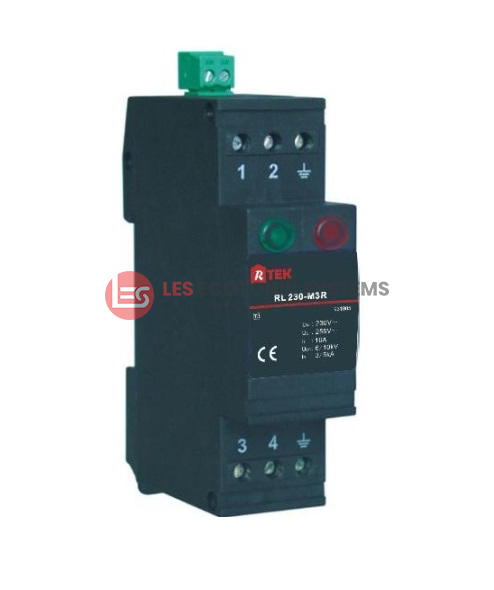
Green light indicates normal and red light indicates fault.
Single phase protection.
Remote signaling connector for fault indication.
3. Application:
RL*-M3R provides fine protection for single phase power of low power supply systems; e.g., refrigerator, air conditioner, photocopy machine, communication equipment, network equipment, and so on.
4. Application Environment:
Temperature: -40℃ … +80℃
Relative humidity: ≤95% (at 25℃)
Technical data
| Part Number | RL 12-M3R | RL 24-M3R | RL 48-M3R | RL 60-M3R | RL 120-M3R | RL 230-M3R |
|---|---|---|---|---|---|---|
| Order No. | 931001 | 931002 | 931003 | 931004 | 931005 | 931006 |
| Nominal a.c. voltage (Un) | 12V | 24V | 48V | 60V | 120V | 230V |
| Rated voltage (max. continuous a.c. voltage Uc) | 14V | 30V | 60V | 75V | 150V | 320V |
| Rated voltage (max. continuous d.c. voltage Uc) | 14V | 30V | 60V | 75V | 150V | 320V |
| Nominal load current (IL) | 16A | 16A | 16A | 16A | 16A | 16A |
| Nominal discharge current (8/20 μs) (line-N/PE) | 2kA | 2kA | 2kA | 3kA | 5kA | 3kA |
| Nominal discharge current (8/20 μs) (L-N/PE(kA)) | 2kA | 2kA | 2kA | 3kA | 5kA | 8kA |
| Combination wave (L-N)(Uoc) | 2kV | 2kV | 2kV | 4kV | 6kV | 6kV |
| Combination wave (L-PE)(Uoc) | 4kV | 4kV | 4kV | 6kV | 10kV | 10kV |
| Voltage protection level (L-N)(Up) | ≤0.12kV | ≤0.24kV | ≤0.35kV | ≤0.5kV | ≤0.7kV | ≤1.15kV |
| Voltage protection level (L-N/PE)(Up) | ≤0.58kV | ≤0.58kV | ≤0.58kV | ≤0.85kV | ≤0.85kV | ≤0.85kV |
| Response time(L-N)(T) | ≤25ns | ≤25ns | ≤25ns | ≤25ns | ≤25ns | ≤25ns |
| Response time(L-N,PE)(T) | ≤100ns | ≤100ns | ≤100ns | ≤100ns | ≤100ns | ≤100ns |
| Max. back up fuse | 16A gL/gG | 16A gL/gG | 16A gL/gG | 16A gL/gG | 16A gL/gG | 16A gL/gG |
| Short-circuit withstand capability at max. Backup fuse | 6kA rms | 6kA rms | 6kA rms | 6kA rms | 6kA rms | 6kA rms |
| Operating temperature range(Tu) | -40°C … +80°C | |||||
| Cross-sectional area | 0.5mm² – 6mm² solid / 4 mm² flexible | |||||
| Mounting on | 35mm DIN rail | |||||
| Enclosure material | Purple thermoplastic, UL94-V0 | |||||
| Dimension | 1.5 mods | |||||
| Type of remote signaling contact | Break contact | |||||
| Switching capacity a.c | 250V/0.5A | |||||
| Switching capacity d.c | 250V/0.1A, 125V/0.2A, 75V/0.5A | |||||
| Cross-sectional area for remote signaling contact | Max. 1.5mm² solid/flexible | |||||
| Test standards | IEC 61643-11 | |||||
| Certification | CE (LVD, EMC) | |||||