Product Introduction
1. Summary:
RL 320-50M2-31R-B is for installation at LPZ 0A-2 or higher, protecting low voltage devices from surge damages, specially designed for TT/TN-S system (“3+1” circuit).
Applied in SPD Class I+II (Class B+C) for various power supply system of lightning current surge protection.
Designed according to IEC 61643-11.
2. Main character:
Three-phase protection for TT/TN-S system (“3+1” circuit).
High discharge capacity, quick response, pluggable.
Double thermal disconnector devices, providing more reliable protection.
Green window will change to red when fault occurs and also provide remote alarm control contact at the same time.
3. Application:
RL 320-50M2-31R-B is applied in Class I+II (Class B+C) TT system.
4. Application environment:
Temperature: -40℃…+80℃
Relative humidity: ≦95% (25°C)
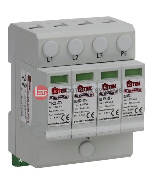
| Model No | RL 320-50M2-31R-B |
|---|---|
| Art.-No. | 923114 |
| Rated voltage (max. continuous a.c voltage) Uc | 320V (L-N), 255V (N-PE) |
| Lightning impulse current (10/350µs) Iimp | 8kA (L-N), 25kA (N-PE) |
| Nominal discharge current (8/20µs) In | 30kA (L-N), 40kA (N-PE) |
| Max. discharge current (8/20µs) Imax | 50kA (L-N), 65kA (N-PE) |
| Voltage protection level Up | ≤ 1.3kV (L-N), ≤ 1.5kV (N-PE) |
| Response time TA | ≤ 25ns (L-N), ≤ 100ns (N-PE) |
| Max. back up fuse | 125A gL/gG |
| MOV Maximum energy (Joule) | 920J (L-N) |
| Operating temperature range | -40℃ … +80℃ |
| Cross-sectional area | 25mm² solid / 35mm² flexible |
| Mounting on | 35mm DIN rail |
| Enclosure material | UL94-V0 |
| Degree of protection | IP20 |
| Dimension | 4 mods |
| Type of remote signaling contact | Switching contact |
| Switching capacity | UN/IN: AC 250V/0.5A, DC 250V/0.1A, 125V/0.2A, 75V/0.5A |
| Cross-sectional area for remote signaling contact | Max. 1.5mm² solid/flexible |
| Test standards | IEC 61643-11 |
| Certification | CE |